Parmec Input Commands
PARMEC input language extends Python. Subroutines related to input processing are listed below. In all cases below, when an object number is returned, indexing starts at 0 and increments on each call.
ARGV
List command line arguments.
list = ARGV (| nonparmec)
list - Python list (possibly empty) of command line arguments
nonparmec - optional boolean flag enabling filtering out parmec arguments; default: True
RESET
Erase all data.
RESET ()
(Can be used to run multiple simulations using one input file)
TSERIES
Create time series: a linear spline based on series of 2-points.
tmsnum = TSERIES (points)
tmsnum - time series number
points - a constant v0, or a list [t0, v0, t1, v1, ….] or [[t0,v0], [t1,v1], …] or [(t0,v0), (t1,v1), …] of points (where ti < tj, when i < j), or a path to a file storing pairs of times and values in format:
# comment 1 …
# comment 2 …
t0 v0
t1 v1
# comment 3 …
t2 v2
…
MATERIAL
Create material.
matnum = MATERIAL (density, young, poisson)
matnum - material number
density - mass density
young - Young modulus
poisson - Poisson ratio
SPHERE
Create a spherical particle.
parnum = SPHERE (center, radius, material, color)
parnum - particle number
center - tuple \(\left(x,y,z\right)\) defining the center
radius - radius
material - material number
color - positive integer surface color
MESH
Create a meshed particle.
parnum = MESH (nodes, elements, material, colors)
parnum - particle number
nodes - list of nodes: [x0, y0, z0, x1, y1, z1, …]
elements - list of elements: [e1, n1, n2, …, ne1, me1, e2, n1, n2, …, ne2, me2, …], where e1 is the number of nodes of the first element, n1, n2, …, ne1 enumerate the element nodes, and me1 is the material number. Similarly for the second and all remaining elements. Supported numbers of nodes per element are 4, 5, 6, and 8 for respectively tetrahedron, pyramid, wedge, and hexahedron, cf. Fig. 80
material - material number
colors - list of positive integer face colors: [gcolor, f1, n1, n2, …, nf1, c1, f2, n1, n2, …, nf2, c2, …], where gcolor is the global color for all not specified faces, f1 is the number of nodes in the first specified face, n1, n2, …, nf1 enumerate the face nodes, and c1 is the surface color of that face. Similarly for the second and all remaining faces. If only the global color is required, it can be passed as [gcolor] or as gcolor alone.
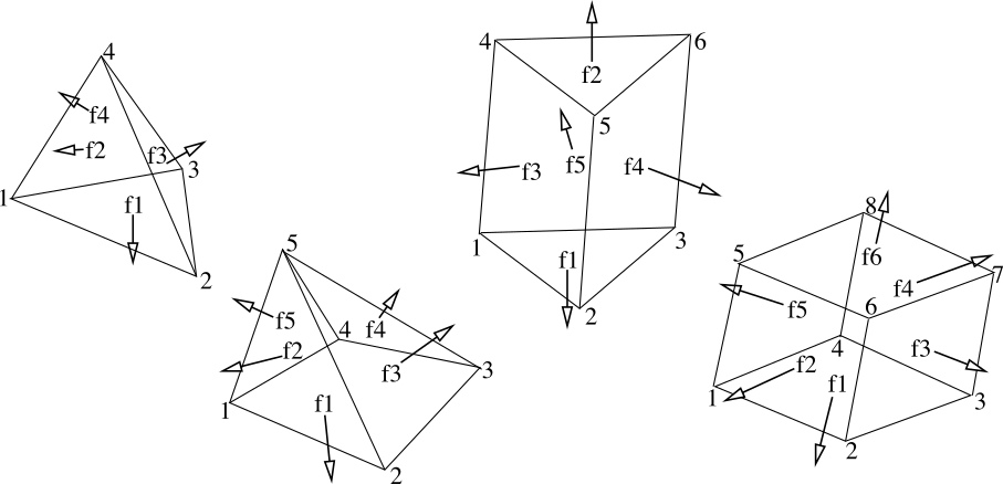
Fig. 80 Mesh element types in Parmec.
ANALYTICAL
Create an analytical particle. Analytical particles have no shapes and are not involved in contact.
parnum = ANALYTICAL ( | inertia, mass, rotation, position, material, particle)
Note, that all parameters are optional.
parnum - particle number
inertia - inertia tensor passed as a list [Ixx, Iyy, Izz, Ixy, Ixz, Iyz]; optional, if particle parameter is used; default [1, 1, 1, 0, 0, 0]
mass - scalar mass; optional, if particle parameter is used; default 1
rotation - optional orientation matrix passed as a list [e1x, e1y, e1z, e2x, e2y, e2z, e3x, e3y, e3z], where vectors e1, e2, e3 are orthonormal; default [1, 0, 0, 0, 1, 0, 0, 0, 1]
position - optional position vector passed as a tuple (x, y, z); default (0, 0, 0)
material - material number; default 0
particle - optional; if specified, an existing particle is converted into an analytical particle; its properties are inherited or overwritten, depending on whether any of the inertia, mass, rotation, position parameters are used; if initially specified, particle shape is inherited and its animated motion is included into the results
OBSTACLE
Create an obstacle.
OBSTACLE (triangles, color | point, linear, angular)
triangles - list of triangle tuples [(t1x1, t1y1, t1z1, t1x2, t1y2, t1z2, t1x3, t1y3, t1z3), (t2x1, t2y1, t2z1, t2x2, t2y2, t2z2, t2x3, t2y3, t2z3), …] defining the obstacle
color - positive integer surface color or a list [color1, color2, …] of colors for each individual triangle
point - spatial reference point
linear - linear velocity history callback: \(\left(v_{x},v_{y},v_{z}\right)=\) linear \(\left(t\right)\)
angular - spatial angular velocity history callback: \(\left(\omega_{x},\omega_{y},\omega_{z}\right)=\) angular \(\left(t\right)\)
SPRING
Create a translational spring constraint. The applied force formula reads
where
The \(\text{spring}\left(\text{stroke}\right)\) and \(\text{dashpot}\left(\text{velocity}\right)\) relationships are defined by means of lookup tables; \(\text{force}\left(t\right)\) is applied at \(\text{point2}\left(t\right)\), and \(-\text{force}\left(t\right)\) is applied at \(\text{point1}\left(t\right)\); dashpot force is not applied when spring force is zero.
sprnum = SPRING (part1, point1, part2, geom2, spring | dashpot, direction, planar, unload, ylim, inactive, offset, friction, kskn) (experimental)
sprnum - spring number
part1 - first particle number
point1 - tuple \(\left(x,y,z\right)\) defining a point moving with the first particle
part2 - second particle number; \(-1\) can be used to indicate a single-particle constraint
geom2 - tuple \(\left(x,y,z\right)\) defining a second point, either moving with the second particle, or a spatial point; alternatively a list storing a point and a normal [\(\left(p_{x},p_{y},p_{z}\right)\), \(\left(n_{x},n_{y},n_{z}\right)\)] defining a referential plane, moving with the second particle or spatially fixed; when a plane is defined the spring direction and stroke are calculated from a projection of point1 onto this plane: in this case the input arguments direction and planar are ignored
spring - spring force lookup table \(\left[\text{stroke}_{1},\text{force}_{1},\text{stroke}_{2},\text{force}_{2},...,\text{stroke}_{n},\text{force}_{n}\right]\); used for both loading and unloading when the unload table and the yield limits are not given
dashpot - optional dashpot force lookup table \(\left[\text{velocity}_{1},\text{force}_{1},\text{velocity}_{2},\text{force}_{2},...,\text{velocity}_{m},\text{force}_{m}\right]\) or a critical damping ratio from interval \(\left[0,+\infty\right)\); default: \(\left[-\infty,0,+\infty,0\right]\)
direction - optional constant direction \(\left(d_{x},d_{y},d_{z}\right)\)
planar - optional planar spring flag; when ’ON’ spring direction \(\left(\text{point2}\left(t\right)-\text{point1}\left(t\right)\right)/\left|\text{point2}\left(t\right)-\text{point1}\left(t\right)\right|\) is projected onto a plane orthogonal to \(\left(d_{x},d_{y},d_{z}\right)\); default: ’OFF’
unload - optional spring unloading lookup table \(\left[\text{stroke}_{1},\text{force}_{1},\text{stroke}_{2},\text{force}_{2},...,\text{stroke}_{n},\text{force}_{n}\right]\); must be monotonically increasing; see also Fig. 81; default: unspecified
ylim - optional tuple \(\left(f_{yc},f_{yt}\right)\) defining the compression, \(f_{yc}\le0\), and tension, \(f_{yt}\ge0\), yield limits; the unloading curve begins to be used once either of these limits is crossed; see also Fig. 81; default: (0, 0)
inactive - optional boolean flag: if True create an inactive spring, that can be activated by the UNSPRING command; default: False
offset - optional TSERIES number representing a time dependent adjustment applied to all stroke values of the spring curve (dashpot unchanged) as in Fig. 82; offset is applied only prior to yielding for springs with ylim and unload specified; default: unspecified
friction - optional tangential friction coefficient; default: 0.0
kskn - optional \(\ge0\) ratio of normal to tangential spring and dashpot parameters used when friction > 0; using kskn = 0 disables tangential springs/dampers and applies frictional force opposing tangential velocity (in this case frictional sticking and stick-slip transition are not modeled); default: 0.0
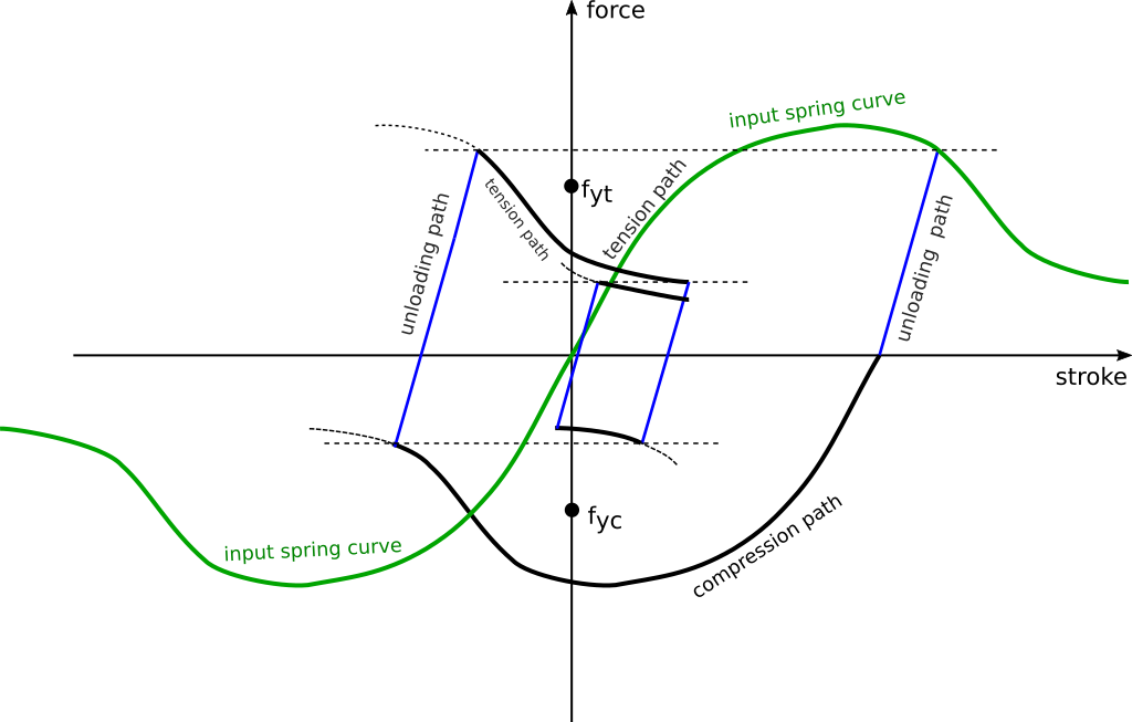
Fig. 81 The type of nonlinear cycles that can be realized using the spring model. Note, that the yield limits do not determine the post-yield behavior: crossing them only activates the unloading curve. Prior to their crossing unloading happens along the original loading curve. Unloading continues until the latest point on the tension or compression path has been reached. Then, this path is continued until the next unloading. During unloading, any path reversals within the latest compression-tension bounds remain on the unloading curve.
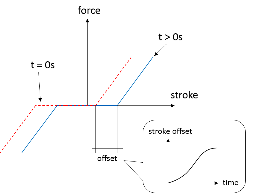
Fig. 82 The concept of time dependent spring stroke offset.
TORSION_SPRING
Create a torsional spring constraint. The applied torque formula reads
where the angles \(\psi\), \(\phi\), \(\theta\) are calculated withe the help of co-rotated unit directions \(\mathbf{x}\), \(\mathbf{y}\), \(\mathbf{z}\) as follows
and where \(\mathbf{\omega}_{i}\) are the spatial angular velocities of particles 1 and 2, and \(\mathbf{\Lambda}_{1}\) is the rigid rotation matrix of particle 1.
trsnum = TORSION_SPRING (part1, part2, zdir, xdir | kroll, kpitch, kyaw, droll, dpitch, dyaw, cone, refpnt) (experimental)
trsnum - torsion spring number
part1 - first particle number
part2 - second particle number; -1 can be used to indicate a single-particle constraint
zdir, xdir - reference direction tuples, \(\mathbf{z}=\left(z_{1},z_{2},z_{3}\right)\) and \(\mathbf{x}=\left(x_{1},x_{2},x_{3}\right)\), co-rotated with the two particles, and used to determine the torsion angles \(\psi\), \(\theta\), \(\phi\) as described above; these directions must be orthogonal
kyaw, kroll, kpitch - spring torque lookup tables \(\left[\text{angle}_{1},\text{torque}_{1},\text{angle}_{2},\text{torque}_{2},...\right]\), about the three torsion angles; default: \(\left[-\infty,0,+\infty,0\right]\)
dyaw, droll, dpitch - dashpot torque lookup tables \(\left[\text{angvel}_{1},\text{torque}_{1},\text{angvel}_{2},\text{torque}_{2},...\right]\) or a critical damping ratio from interval \(\left[0,+\infty\right)\); default: \(\left[-\infty,0,+\infty,0\right]\)
cone - optional tuple (‘roll’, ‘yaw’), (‘roll’, ‘pitch’), (‘pitch’, ‘yaw’) or (‘roll’, ‘pitch’, ‘yaw’) denoting a cone constraint in the (roll, pitch, yaw) angle space; the spring/dashpot torque curves of the first in (roll, pitch, yaw) order coordinate are used (hence it makes sense to define at least one of these curves), e.g. both (‘roll’, ‘pitch’) and (‘pitch’, ‘roll’) result in torque formula \(\mathbf{t}=\left[\text{kroll}\left(\sqrt{\psi^{2}+\phi^{2}}\right)+\text{droll}\left(\frac{d}{dt}\sqrt{\psi^{2}+\phi^{2}}\right)\right]\left[\frac{\psi}{\sqrt{\psi^{2}+\phi^{2}}}\mathbf{x}+\frac{\phi}{\sqrt{\psi^{2}+\phi^{2}}}\mathbf{y}\right]\), etc.; default: not specified
refpnt - a reference point moving with part1, used to position in space the OUTPUT vector fields; default: \(0.5\left(\text{centre}\left(\text{part1}\right)+\text{centre}\left(\text{part2}\right)\right)\) or \(\text{centre}\left(\text{part1}\right)\) when part2 = -1
UNSPRING
Undoes user defined selection of springs (msprings) based on the value of spring entities experienced by a different user defined selection of springs (tsprings). Modifications to the spring curves occur during a simulation. Undone springs remain in the simulation but generate zero forces.
UNSPRING (tsprings, msprings, limits | entity, operator, abs, nsteps, nfreq, unload, activate) (experimental)
tsprings - list of unique spring numbers whose spring entities are assessed against a criteria defined by limits; must be nonempty
msprings - list of unique spring numbers which are to be modified if tsprings meet the limits criteria (springs defined in tsprings are not modified unless also specified in msprings); must be nonempty
limits - tuple of (min, max) tsprings operator entity limit values which need to be exceeded for msprings to be modified; if either value is None then no failure limit is assumed e.g. (None, max) only has an upper failure limit; also min < max
entity - scalar spring entity string: (spring stroke) ‘STROKE’, (spring total force) ‘F’, (spring force without damping) ‘SF’, (spring total friction force) ‘FF’, cf. HISTORY and OUTPUT; default: ‘SF’
operator - collective tsprings operator string: ‘SUM’, ‘MIN’, ‘MAX’; default: ‘SUM’
abs - boolean, if True then spring forces are converted to absolute values before summation of the spring forces; default: False
nsteps - int, number of time steps between calls of UNSPRING; default: 1
nfreq - int, number of nsteps for which tsprings exceed limits before msprings are modified; default: 1
unload - Python dictionary (i.e. unload [key] = value), where key (int) - unique spring number (must be present in msprings) and value (int) - time series number (TSERIES) defining the unload spring curve; an unloading curve must originate at zero and increase monotonically; once modification is activated, for each spring in msprings, the unloading curve is individually applied with a shift specific to the current displacement; both negative and positive displacement increments decrease total spring forces until zero; the spring force remains zero ever after; dashpot force is zero during unloading; default: instantaneous unloading to zero total force
activate - a list of inactive SPRING numbers that will be activated upon complete unloading of all msprings; default: empty
By default, modification of msprings is based on the sum of the elastic spring force values across all spring numbers defined in tsprings. This is a sum of absolute values if abs = True. Forces in all tsprings must exceed the specific min/max values defined in limits for the spring curves to be modified (i.e. spring curve modification is an and operation, not or). For example:
tsprings = (1,2)
msprings = (3,4)
limits = (-1.0, 1.0)
UNSPRING(tsprings, msprings, limits)
results in the resultant elastic spring force (SF) being assessed against the (-1.0, 1.0) limits. For the spring curves of springs 3 and 4 to be modified, the sum of the forces of springs 1 and 2 must be outside of the (-1.0,1.0) limits for nfreq (=1) number of nsteps (=1).
BALL_JOINT
Create a ball joint between two particles at a coincident point. The joint is modeled as an algebraic constraint, without affecting the stable time step. Any number of joints between any number of particles can be added. A linear system is solved at every time step to calculate joint forces.
jnum = BALL_JOINT (part1, point | part2) (experimental)
jnum - joint number
part1 - first particle number
point - coincident point \(\left(x,y,z\right)\)
part2 - optional second particle number; default: not specified (in this case part1 is fixed in space at point)
EQM
Calculate equivalent point mass from particle inertia and mass properties. Two particles can be passed for relative motion mass. This subroutine can be used to calculate linear stiffness and damping properties for spring based constraints, e.g. \(\text{stiffness}=\text{acceleration}\cdot\text{EQM}/\text{leeway}\) and \(\text{damper}=\text{damping ratio}\cdot2\cdot\sqrt{\text{mass}\cdot\text{stiffness}}\) can be used to define spring and dashpot curves as \(\left[-1,-\text{spring},1,\text{spring}\right]\) and \(\left[-1,-\text{damper},1,\text{damper}\right]\) respectively, with the critical time step equal to \(\left(2/\sqrt{\text{stiffness}\cdot\text{mass}}\right)\cdot\left(\sqrt{1+\text{damper}^{2}}-\text{damper}\right)\).
mass = EQM (part1, point1 | part2, point2, direction) (experimental)
mass - equivalent point mass
part1 - particle number
point1 - point coordinates
part2 - optional second particle number; default: not specified
point2 - optional second particle point coordinates; default: not specified
direction - optional direction of motion; default: not specified
GRANULAR
Define surface pairing for the granular contact interaction model. Default parameters, for unspecified pairings, are: spring = 0.0, damper = 1.0, friction = (0.0, 0.0), rolling = 0.0, drilling = 0.0, and kskn = 0.5.
GRANULAR (color1, color2, spring | damper, friction, rolling, drilling, kskn)
color1 - first color (positive, or color1 = 0 and color2 = 0 to redefine default parameters for unspecified pairings)
color2 - second color (positive, or color1 = 0 and color2 = 0 to redefine default parameters for unspecified pairings)
spring - normal spring constant
damper - optional normal damping ratio; default: 1.0
friction - optional Coulomb’s friction coefficient; default: 0.0; tuple \(\left(\mu_{s},\mu_{d}\right)\) can be used to specify respectively static and dynamic friction coefficients; (experimental)
rolling - optional rolling friction coefficient; default: 0.0; (under development)
drilling - optional drilling friction coefficient; default: 0.0; (under development)
kskn - optional ratio of normal to tangential spring and dashpot parameters; default: 0.5
RESTRAIN
Restrain particle motion.
RESTRAIN (parnum | linear, angular)
parnum - particle number
linear - list \(\left[x_{1},y_{1},z_{1}\right]\), \(\left[x_{1},y_{1},z_{1},x_{2},y_{2},z_{2}\right]\), or \(\left[x_{1},y_{1},z_{1},x_{2},y_{2},z_{2},x_{3},y_{3},z_{3}\right]\) defining directions of restrained linear motion; default: \(\left[0,0,0\right]\)
angular - list \(\left[x_{1},y_{1},z_{1}\right]\), \(\left[x_{1},y_{1},z_{1},x_{2},y_{2},z_{2}\right]\), or \(\left[x_{1},y_{1},z_{1},x_{2},y_{2},z_{2},x_{3},y_{3},z_{3}\right]\) defining directions of restrained spatial rotation; default: \(\left[0,0,0\right]\)
PRESCRIBE
Prescribe particle motion. Prescribed motion overwrites this resulting from dynamics and restraints.
PRESCRIBE (parnum | linear, angular, kind)
parnum - particle number
linear - a tuple \((i,j,k)\) of TSERIES numbers, or a callback: \(\left(v_{x},v_{y},v_{z}\right)=\) linear \(\left(t\right)\), defining linear velocity or acceleration history; default: not prescribed
angular - a tuple \((i,j,k)\) of TSERIES numbers, or a callback: \(\left(\omega_{x},\omega_{y},\omega_{z}\right)=\) angular \(\left(t\right)\), defining spatial angular velocity or acceleration history; default: not prescribed
kind - string ’vv’, ’va’, ’av’, or ’aa’ indicating interpretation of respectively linear and angular time histories as either velocity or acceleration; default: ’vv’
VELOCITY
Set particle velocity.
VELOCITY (parnum | linear, angular)
parnum - particle number
linear - linear velocity tuple \(\left(v_{x},v_{y},v_{z}\right)\); default: \(\left(0,0,0\right)\) at \(t=0\)
angular - angular velocity tuple \(\left(\omega_{x},\omega_{y},\omega_{z}\right)\); default: \(\left(0,0,0\right)\) at \(t=0\)
GRAVITY
Set gravity.
DAMPING
Set global damping, applied as
where \(m\) is scalar mass, \(v\) is linear velocity, \(\mathbf{\Lambda}\) is the rotation matrix, \(\mathbf{J}\) is the referential inertia matrix, and \(\omega\) is spatial angular velocity.
DAMPING (linear, angular)
linear - linear damping curve callback \(\left(d_{vx},d_{vy},d_{vz}\right)=\) linear \(\left(t\right)\), or a tuple \((i,j,k)\) of TSERIES numbers
angular - angular damping curve callback \(\left(d_{\omega x},d_{\omega y},d_{\omega z}\right)=\) angular \(\left(t\right)\), or a tuple \((i,j,k)\) of TSERIES numbers
CRITICAL
Estimate critical time step. By default this routine returns an estimate in the area of a practical stable step. When run with the optional parameter \(\text{perspring}=n\) it will return a list of lowest estimates for \(n\) individual springs. Similarly, when run with the optional parameter \(\text{perparticle}=n\) it will return a list of lowest estimates for \(n\) individual particles. The actual stable time step may be a factor of \(\left[0.1,10\right]\) away of the returned step (estimated), depending on the degree of nonlinearity of the system. See also.
h = CRITICAL (| perspring, perparticle)
h - critical time step (when run without parameters), or a list \(\left[\left(h_{1},i_{1},\omega_{1},\xi_{1}\right),...,\left(h_{n},i_{n},\omega_{n},\xi_{n}\right)\right]\) when perspring \(=n\) or perparticle \(=n\) is used, where \(h_{k}\) is the per-spring/particle critical time step estimate, \(i_{k}\) is the spring/particle index, \(\omega_{k}\) is the maximum spring/particle circular frequency, and \(\xi_{k}\) is the maximum spring/particle damping ratio; when both parameters perspring \(=n\) and perparticle \(=m\) are used, a tuple of two corresponding lists is returned (\(\left[\left(h_{1},i_{1},\omega_{1},\xi_{1}\right),...,\left(h_{n},i_{n},\omega_{n},\xi_{n}\right)\right]\), \(\left[\left(h_{1},i_{1},\omega_{1},\xi_{1}\right),...,\left(h_{m},i_{m},\omega_{m},\xi_{m}\right)\right]\))
perspring - optional integer \(n\) indicating the number of lowest per-spring critical time step estimates; default: undefined
perparticle - optional integer \(n\) indicating the number of lowest per-particle critical time step estimates; default: undefined
HISTORY
Before running a simulation, request time history output.
list = HISTORY (entity | source, point, h5file, h5last)
list - output time history list (empty upon initial request, populated during simulation)
entity - entity name; global entities: (output time) ’TIME’; particle entities: (position) ’PX’, ’PY’, ’PZ’, ’|P|’, (displacement) ’DX’, ’DY’, ’DZ’, ’|D|’, (linear velocity) ’VX’, ’VY’, ’VZ’, ’|V|’, (angular velocity) ’OX’, ’OY’, ’OZ’, ’|O|’, (body force) ’FX’, ’FY’, ’FZ’, ’|F|’, (body torque) ’TX’, ’TY’, ’TZ’, ’|T|’; linear spring entities: (spring length) ‘LENGTH’, (spring stroke) ’STROKE’, (spring total force) ’F’, (spring force without damping) ’SF’, (spring total friction force) ‘FF’, (spring state) ‘SS’, cf. OUTPUT for description; torsional spring entities: (spring local direction components: \(\mathbf{z}\) - yaw, \(\mathbf{x}\) - roll, and \(\mathbf{y}=\mathbf{z}\times\mathbf{x}\) - pitch) ‘ZDIR_X’, ‘ZDIR_Y’, ‘ZDIR_Z’, ‘XDIR_X’, ‘XDIR_Y’, ‘XDIR_Z’, (spring rotation angles) ‘ROLL’, ‘PITCH’, ‘YAW’, (spring total moment components: r - roll, p - pitch, y - yaw) ‘TRQTOT_R’, ‘TRQTOT_P’, ‘TRQTOT_Y’, (spring undamped moment components) ‘TRQSPR_R’, ‘TRQSPR_P’, ‘TRQSPR_Y’; joint entities: ‘(joint reaction) ‘JREAC_X’, ‘JREAC_Y’, ‘JREAC_Z’, ‘|JREAC|’
source - particle number i, or a list of particle numbers [i, j, …], or a spatial sphere defined as tuple \(\left(x,y,z,r\right)\) (under development), or a spatial box defined as tuple \(\left(x_{\text{min}},y_{\text{min}},z_{\text{min}},x_{\text{max}},y_{\text{max}},z_{\text{max}}\right)\) (under development); in case of a list of particle numbers the output entity is averaged over the set of particles; in case of a spatial sphere or box the output entity is averaged over the set of particles passing through it (under development); default: 0 (useful when entity is ’TIME’); spring/joint number or a list of numbers can be used as a source in case of spring/joint entities
point - optional referential point used in case of a single particle source; default: particle mass centre
h5file (experimental) - optional .h5 file storing existing results; in this case the history is retrieved from this file (if found) or an error message is issued; an appropriate output file needs to be picked depending on the entity, cf. OUTPUT; the output list is not populated until h5last = True; default: not specified
h5last (experimental) - optional boolean flag marking a last call to HISTORY for which the h5file argument is used; for faster reading all such histories are populated once HISTORY(…, h5file = …, h5last = True) is called; default: False
OUTPUT
Before running a simulation, define scalar and/or vector entities included into the output file(s). PARMEC outputs:
*0.dump files for spherical particles not specified as a subset in the OUTPUT command
*1.dump, *2.dump, … files for spherical particles specified as subsets, where numbers 1, 2, … match consecutive OUTPUT calls
*0.vtk.* and/or (*0.h5, *0.xmf) and/or (*0.med) files for obstacles and mesh based particles not specified as a subset in the OUTPUT command
*1.vtk.*, *2.vtk.*, … and/or (*1.h5, *1.xmf, *2.h5, *2.xmf, …) and/or (*1.med, *2.med…) files for mesh based particles specified as subsets, where numbers 1, 2, … match consecutive OUTPUT calls
*0rb.vtk.* and/or (*0rb.h5, *0rb.xmf) and/or (*0rb.med) files for rigid body data of particles not specified as a subset in the OUTPUT command
*1rb.vtk.*, *2rb.vtk.*, … and/or (*1rb.h5, *1rb.xmf, *2rb.h5, *2rb.xmf, …) and/or (*1rb.med, *2rb.med, …) files for rigid body data of particles specified as subsets, where numbers 1, 2, … match consecutive OUTPUT calls
*0cd.vtk.* and/or (*0cd.h5, *0cd.xmf) and/or (*0cd.med) files for contact data including particles not specified as a subset in the OUTPUT command
*1cd.vtk.*, *2cd.vtk.*, … and/or (*1cd.h5, *1cd.xmf, *2cd.h5, *2cd.xmf, …) and/or (*1cd.med, *2cd.med, …) files for contact data including particles specified as subsets, where numbers 1, 2, … match consecutive OUTPUT calls
*0sl.vtk.* and/or (*0sl.h5, *0sl.xmf) and/or (*0sl.med) files for linear spring data including particles not specified as a subset in the OUTPUT command
*1sl.vtk.*, *2sl.vtk.*, … and/or (*1sl.h5, *1sl.xmf, *2sl.h5, *2sl.xmf, …) and/or (*1sl.med, *2sl.med, …) files for linear spring data including particles specified as subsets, where numbers 1, 2, … match consecutive OUTPUT calls
*0st.vtk.* and/or (*0st.h5, *0st.xmf) and/or (*0st.med) files for torsional spring data including particles not specified as a subset in the OUTPUT command
*1st.vtk.*, *2st.vtk.*, … and/or (*1st.h5, *1st.xmf, *2st.h5, *2st.xmf, …) and/or (*1st.med, *2st.med, …) files for torsional spring data including particles specified as subsets, where numbers 1, 2, … match consecutive OUTPUT calls
*0jt.vtk.* and/or (*0jt.h5, *0jt.xmf) and/or (*0jt.med) files for joints data including particles not specified as a subset in the OUTPUT command
*1jt.vtk.*, *2jt.vtk.*, … and/or (*1jt.h5, *1jt.xmf, *2jt.h5, *2jt.xmf, …) and/or (*1jt.med, *2jt.med, …) files for joints data including particles specified as subsets, where numbers 1, 2, … match consecutive OUTPUT calls
OUTPUT ( | entities, subset, mode, format)
entities - list of output entities; default: [’NUMBER’, ’COLOR’, ’DISPL’, ’LENGTH’, ’ORIENT’, ‘ORIENT1’, ‘ORIENT2’, ‘ORIENT3’, ’LINVEL’, ’ANGVEL’, ’FORCE’, ’TORQUE’, ’F’, ’FN’, ’FT’, ’SF’, ’FF’, ’SS’, ’AREA’, ’PAIR’, ‘XDIR’, ‘YDIR’, ‘ZDIR’, ‘TRQROT’, ‘TRQTOT’, ‘TRQSPR’] where:
’NUMBER’ - scalar field of particle numbers (modes: ’SPH’, ’MESH’, ’RB’), or scalar field of spring/joint numbers (modes: ’SL’, ‘ST’, ‘JT’)
’COLOR’ - scalar field of surface colors (modes: ’SPH’, ’MESH’), or 2-component vector field of contact surface colors (modes: ’CD’)
’DISPL’ - 3-component vector field of displacements (modes: ’SPH’, ’MESH’, ’RB’), or scalar field of contact depths (modes: ’CD’), or scalar field of spring strokes (modes: ’SL’)
’LENGTH’ - scalar field of spring lengths (modes: ‘SL’)
’ORIENT’ - 9-component tensor field representing rigid rotation matrix (modes: ‘RB’), or 3-component vector field of spring orientations (modes: ’SL’)
’ORIENT1’, ‘ORIENT2’, ‘ORIENT3’ - three 3-component vector fields representing columns of rigid rotation matrix (orientation vectors) (modes: ’RB’)
’LINVEL’ - 3-component vector field of linear velocity (modes: ’SPH’, ’MESH’, ’RB’)
’ANGVEL’ - 3-component vector field of (spatially constant) angular velocity (modes: ’SPH’, ’MESH’, ’RB’)
’FORCE’ - 3-component vector field of (spatially constant) total body force (modes: ’SPH’, ’MESH’, ’RB’)
’TORQUE’ - 3-component vector field of (spatially constant) total body torque (modes: ’SPH’, ’MESH’, ’RB’)
’F’ - 3-component vector field of total contact forces (modes: ’CD’), or scalar field of total spring forces (modes: ’SL’)
’FN’ - 3-component vector field of normal contact forces (modes: ’CD’)
’FT’ - 3-component vector field of tangential contact forces (modes: ’CD’)
’SF’ - scalar field of spring force magnitude, without dashpot contribution (modes: ’CD’, ’SL’)
’FF’ - scalar field of total friction force magnitude (modes: ’CD’, ’SL’)
- ‘SS’ - scalar field of spring states, where -3.0 denotes a regular spring (always active),
-2.0 denotes an active spring, -1.0 denotes a deactivated spring (zero force), and values \(\ge0\) denote a spring currently being unloaded (the number itself denotes TSERIES used as an unloading curve) (modes: ‘SL’)
’AREA’ - scalar field of contact area (modes: ’CD’)
’PAIR’ - 2-component vector field of particle pair numbers (modes: ’CD’, ’SL’)
‘XDIR’ - 3-component vector field of x-directions (roll rotation) for torsion springs (modes: ‘TS’)
‘YDIR’ - 3-component vector field of y-directions (pitch rotation) for torsion springs (modes: ‘TS’)
‘ZDIR’ - 3-component vector field of z-directions (yaw rotation) for torsion springs (modes: ‘TS’)
‘TRQROT’ - 3-component vector field of a relative rotation of torsion springs in global coordinates (modes: ‘TS’); use dot products to retrieve local rotation angles, e.g. \(\text{TRQROT}\cdot\text{XDIR}\) will give roll, etc.
‘TRQTOT’ - 3-component vector field of total torques of torsion springs in global coordinates (modes: ‘TS’); use dot products to retrieve components conjugate to (roll, pitch, yaw) angles, e.g. \(\text{TRQROT}\cdot\text{YDIR}\) will give the pitch-conjugate component, etc.
‘TRQSPR’ - 3-component vector field of spring torques (without dampers) of torsion springs in global coordinates (modes: ‘TS’); use dot products to retrieve components conjugate to (roll, pitch, yaw) angles, e.g. \(\text{TRQSPR}\cdot\text{ZDIR}\) will give the yaw-conjugate component, etc.
‘JREAC’ - 3-component vector field of joint reactions (modes: ‘JT’)
subset - optional particle number i, or a list of particle numbers [i, j, …], to which this specification is narrowed down
mode - optional output mode or list of output modes: ’SPH’ for sphere output, ’MESH’ for mesh output, ’RB’ for rigid body output, ’CD’ for contact data output, ’SL’ for linear spring data output, ’ST’ for linear spring data output, ‘JT’ for joints data output; default: [’SPH’, ’MESH’, ’RB’, ’CD’, ’SL’, ’ST’, ‘JT’]
format - optional output format, e.g. ‘DUMP’ (experimental/under development) or ‘VTK’ or ‘XDMF’ or ‘MED’ (experimental/under development), or a list e.g. [‘DUMP’, ‘VTK’, ‘XDMF’, ‘MED’], where ‘DUMP’ is the text based LAMMPS format (experimental/under development), ‘VTK’ is the text based legacy VTK format, ‘XDMF’ is the HDF5/XML based XDMF format, and ‘MED’ is the binary MED format (experimental/under development); default: ‘XDMF’
DEM
Run DEM simulation.
t = DEM (duration, step | interval, prefix, adaptive)
t - simulation runtime in seconds
duration - simulation duration
step - time step; initial if adaptive is used or constant otherwise
interval - output interval (default: time step); tuple \(\left(dt_{\text{files}},dt_{\text{history}}\right)\) can be used to indicate different output frequencies of output files and time histories, respectively; callback functions or TSERIES numbers can also be used, e.g. \(dt_{\text{files}}=\text{dt_fiels}\left(t\right)\) and \(dt_{\text{history}}=\text{tmsnum}\), prescribing variable interval frequencies, depending on current time;
prefix - output file name prefix (default: input file name without the “.py” extension); Note: prefix can only change at time 0.0 or after RESET()
adaptive - adaptive time step reduction factor; zero turns off adaptive time stepping, values \(>0.0\) and \(\le1.0\) turn it on; default: \(0.0\) (experimental)